Dynamics & Control Labs
AE 443 · Experimental Dynamics and Control Laboratory · Spring 2026 · ERAU
Lab 01: Servo Modeling
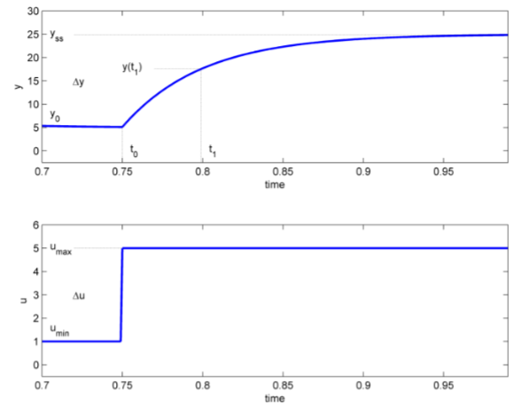
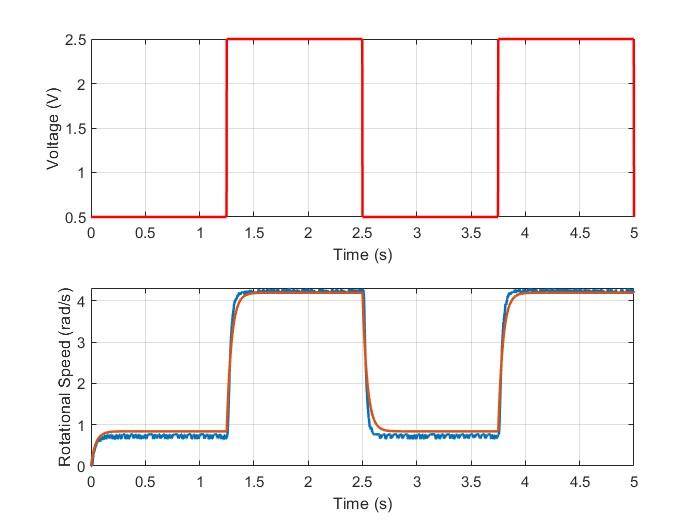
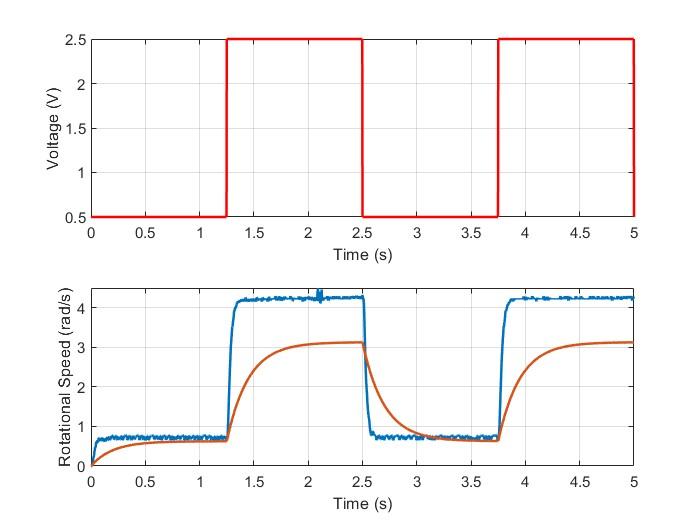
Applied a square-wave step input to the Quanser SRV02 servo-motor and recorded the load shaft speed response via MATLAB/Simulink to extract steady-state gain (K) and time constant (τ) using the bump test method. Iterated model parameters in a validation experiment; best-fit values of K = 1.68 rad/s/V and τ = 0.044 s produced near-exact agreement between simulated and measured responses.
Lab 02: Flexible Link Modeling
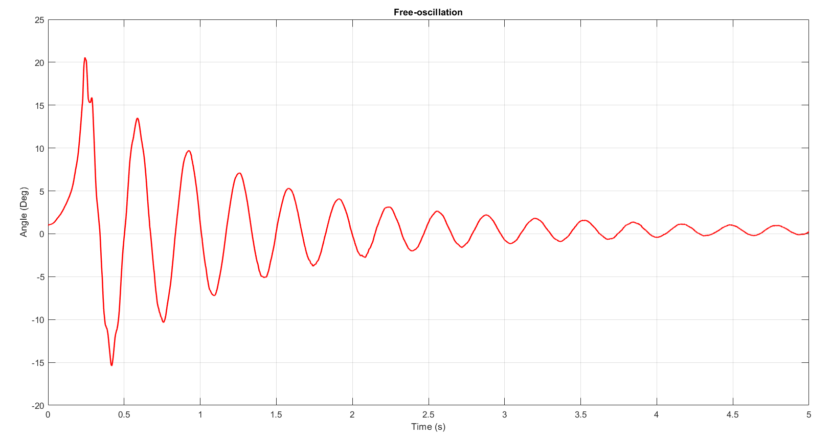
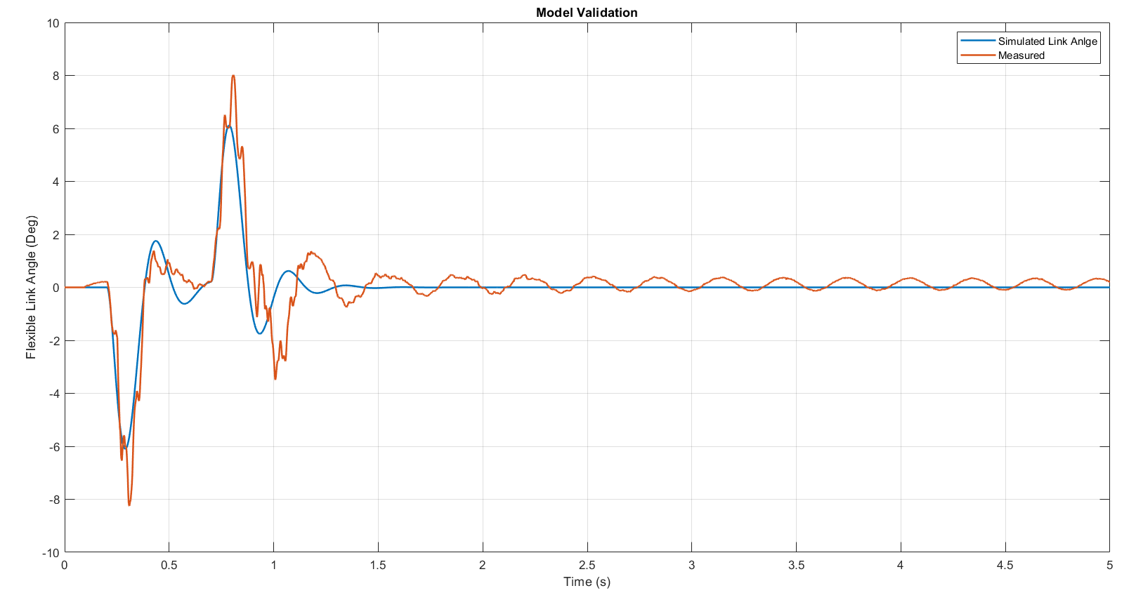
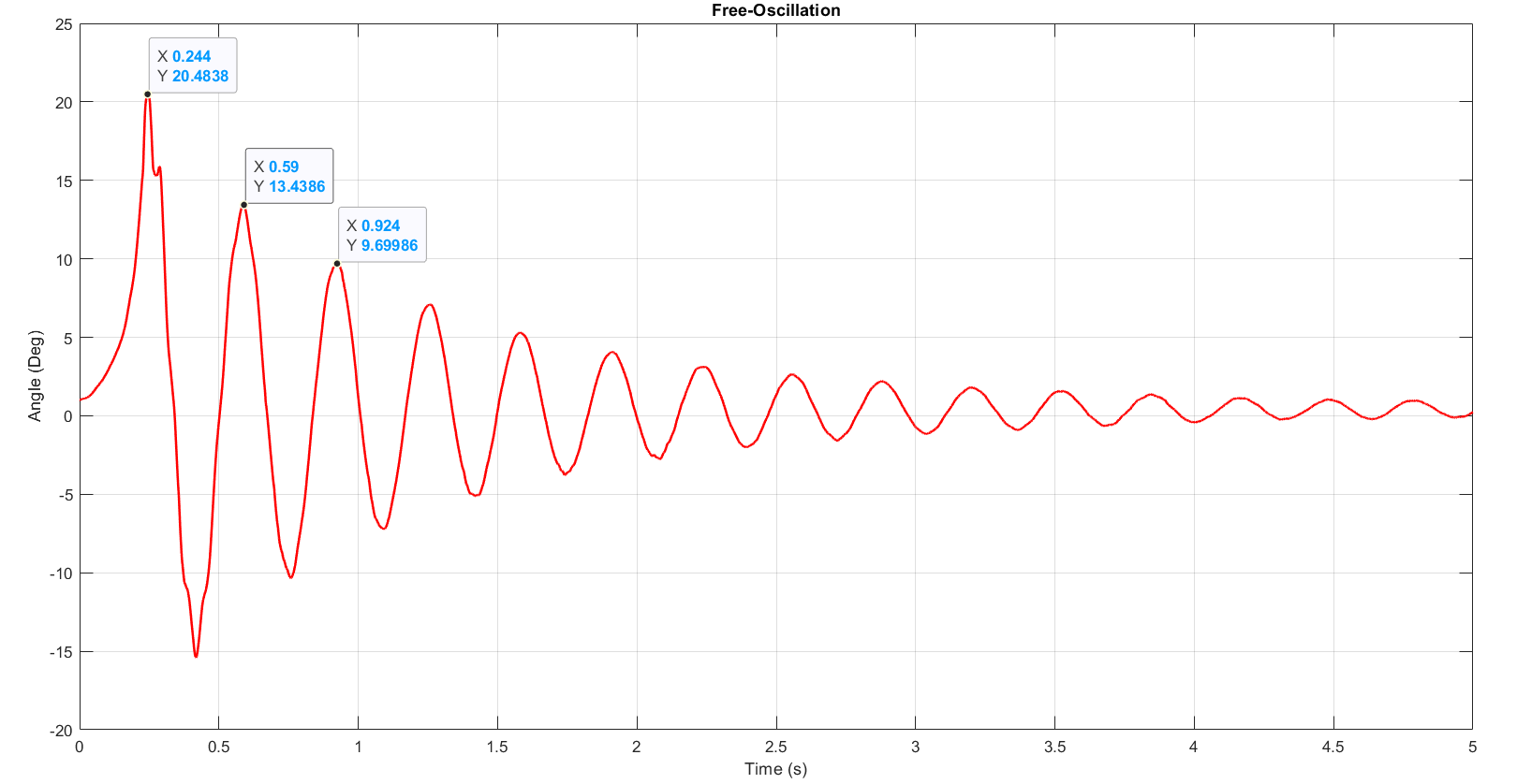
Derived equations of motion for the SRV02 rotary flexible link using the Euler-Lagrange method, then identified the link's natural frequency (ωn = 18.49 rad/s) and stiffness (K_s = 1.30 N·m/rad) from a free-oscillation response. Built and validated a 4-state state-space model; open-loop poles and transfer functions were derived and compared against measured servo angle and link angle responses.
Lab 03: SRV02 Position Control
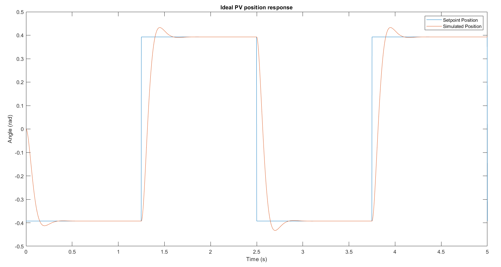
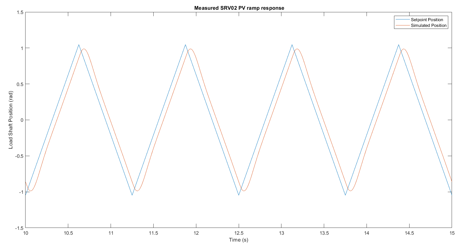
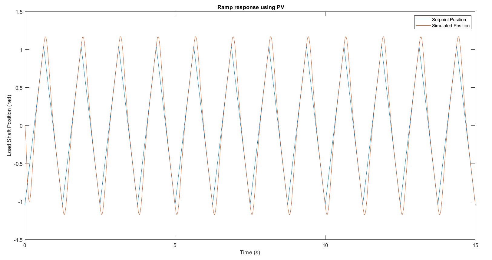
Designed PV and PIV controllers for load shaft position control of the SRV02. Step tracking was validated in simulation and on hardware; adding an integral gain k_i = 38.9 V/(rad·s) reduced ramp tracking steady-state error from 0.186 rad (PV alone) to 0.007 rad (PIV), confirming that the integral term eliminates the Type-1 ramp error present in PV-only control.
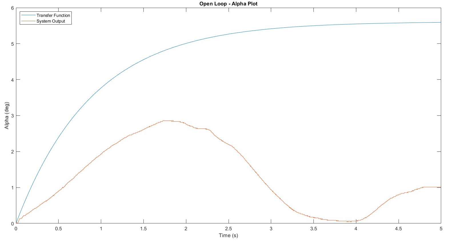
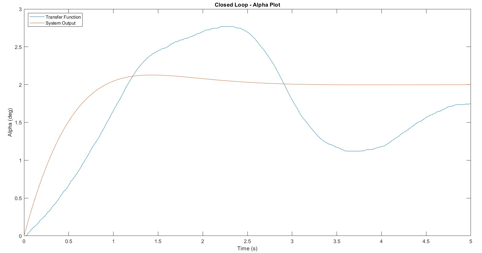
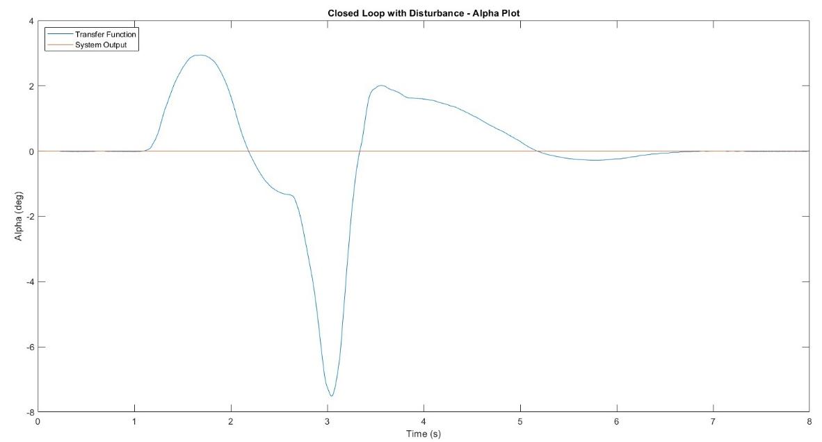
Lab 04: Gyro Modeling and Control
Derived the closed-loop transfer function for a PI-controlled rotary gyroscope and designed gains (k_p = 19.79, k_i = 39.86) to track a 2° deflection reference. Demonstrated superior disturbance rejection with the PI controller enabled versus disabled, and confirmed system stability for both open-loop and closed-loop configurations using the Routh-Hurwitz criterion.
Lab 05: Speed Control
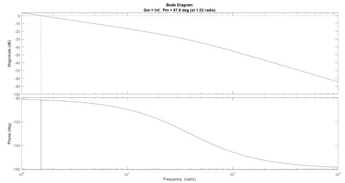
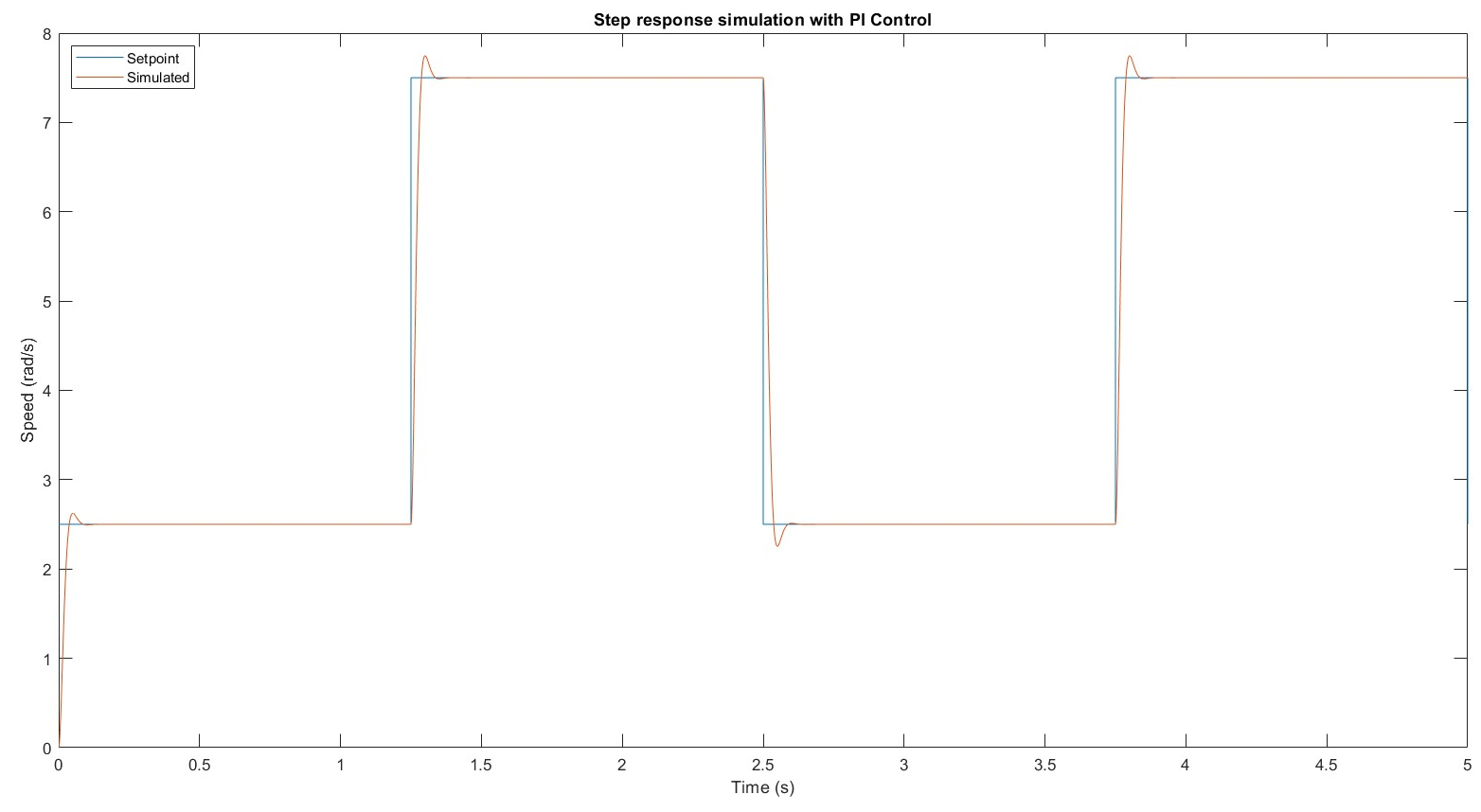
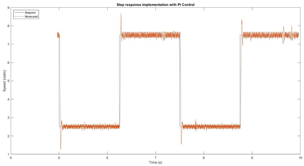
Designed and compared PI and lead compensators for SRV02 motor speed regulation using frequency-domain methods. Bode analysis confirmed infinite gain margin and 87.8° phase margin. PI control achieved 4.4% overshoot in simulation and 23.8% on hardware; the lead compensator showed 2% simulated overshoot but 44.4% on hardware, demonstrating that PI control is more robust to unmodeled physical effects in this configuration.